Last time, we saw how to start with our dev board, we analyzed the feasibility of the project and get our hand around IceStudio. We succeed in turning on the LED, only when the button is pressed. When we release the button, the LED turn off. Now it is time to design something more advanced and ask ourselves this question :
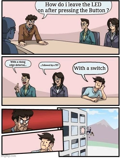
Of course we could use a switch. Just replace the button with a switch if your board has one, in the previous article and it works. It is actually a reality of the professional world : a trade off between the hardware, the FPGA and the software often occurrs. The “switch” solution here, make the trades to design the hardware to support the feature instead of the FPGA. And it is actually your hardware colleagues who are going to throw you out through the window for asking that change. And since it is less expensive to reconfigure an FPGA than redesign a board, the FPGA is more likely to implement the change for a pre-existing product… unless some software is involved then you can offload the work to the software engineers HAHAHA (don’t do that either).
Let’s make the decision to implement the feature inside the FPGA and learn something new. After all, that’s why we are here.
It is time to apply the theory we saw on my previous article about DFF. For this we are going to implement a rising edge detector and a TFF/divider by two, which are basics designs built around DFFs … like every others. But those two are particularly simple and useful in nearly every design. They are among the basic digital design a beginner should know.
1.Descritpion of the new specification.
Let’s describe the state of the project more precisely. Right now the LED reproduces the STATE of our button PRESSED = ON and RELEASED = OFF. Which in gherkin language (a very simple specification language, I will do an article about it later) is described like this :
Scenario: pressing the button
    When I press the button
    Then the LED is turned on

Scenario : Releasing the button
    Given the button is pressed
    When I release the button
Then the LED turns offScenario: pressing the button
When I press the button
Then the LED is turned on
Scenario : Releasing the button
Given the button is pressed
When I release the button
Then the LED turns offWhat we want is:
Scenario: pressing the button
    Given the LED has two states ON and OFF
    And that the LED is in one of those state
    When I press the button
Then the LED state should toggle to the other state There is a better way to write it but I don’t want to confuse you with a language that I did not introduce. At least you know the name and you can now look for yourself if you are curious.
2. The T flip-flop or Divider by two
So this second description above help us to know what we need. We have to store the state of the LED which is ON = 1, OFF = 0. Amazing ! This info fits in DFF. So when the LED is ON and I press the button then the LED is OFF or, in other words : NOT ON. In Verilog it translates easily with the following code.
always @(posedge clk)
begin
    if(press_event)
        next_state <= ~current_state; // next state is "not current state"
end And in IceStudio like this (“how to” in the last part):
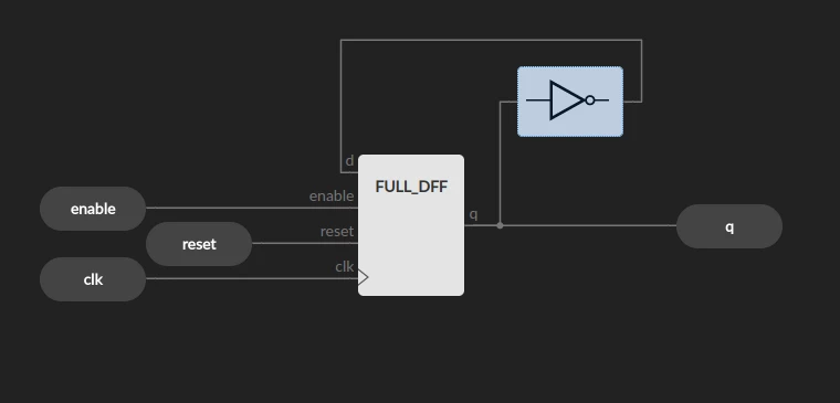
This module is called a TFF (Toggle flip-flop). When “enable” is asserted the output “q” is toggled. I heard it to be also called “divider by two” because the output “q” will be asserted once every two assertions of “enable”.
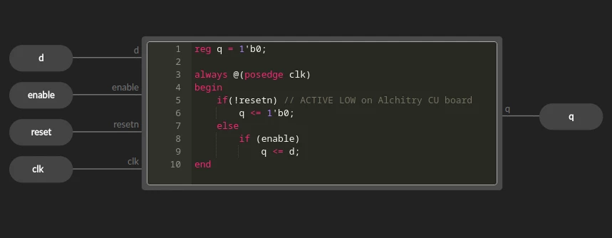
The default DFF and TFF in Icestudio do not expose enable, nor the clock and reset. So I made my own DFF called “FULL_DFF” on the photo. Which is simply the following code.
With this we can save the state of the LED (ON or OFF). But how do we manage the “enable” of the TFF ? Indeed if you try to connect the button directly to the “enable” of the TFF and press continuously on the button, you will get a dim light on the LED and it will randomly stay ON or OFF after releasing. What is this new devilry ?
When you press continuously on the button, “enable” is asserted. Which means the TFF will toggle the state of the LED (ON then OFF) at the clock frequency (100Mhz). This is the equivalent of pressing the button of the last article 100 million times per second. The dim light is just your LED been ON for 20ns and OFF for the next 20ns, 50 million times per second. Physically, your LED won’t fully turn ON or OFF at this rate, but it will still receive only half the energy it needs to be fully turn on. So the dim light is your LED turned on at 50% of its full brightness. The LED state inside the FPGA toggle so fast that when you release the button you cannot predict its state with your mere mortal senses, thus the apparent randomness. It is actually the way we will control servo motors, but that’s another topic for another article.
3. Rising Edge Detection.
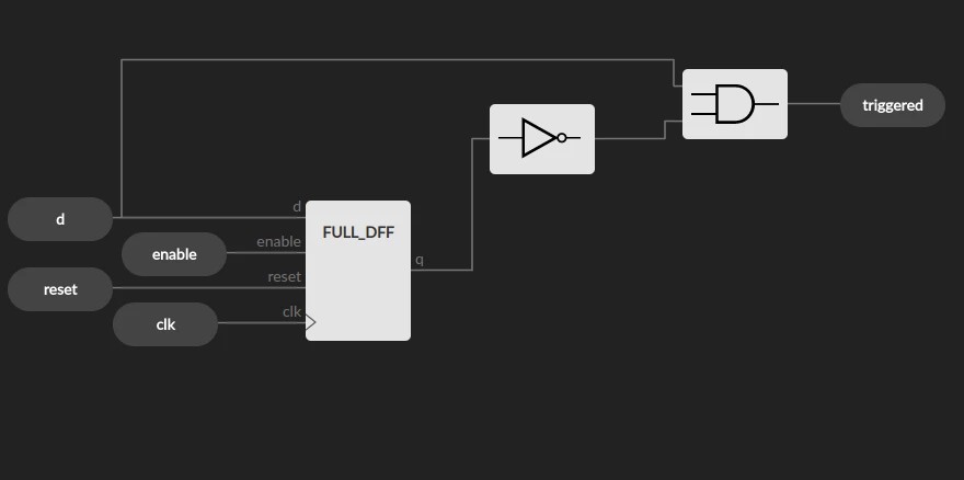
Now there is one question left: how do we detect the event of pressing the button ? For this we need to store the state of the button. You guessed it, we need another DFF. If we connect the button to the input “d” of the DFF, “q” will be the state of the button of the last period. The event of pressing the button is when the previous state (q) is “NOT PUSHED” and the current state (d) is “PUSHED”.
always @(posedge clk)
begin
    q <= d;
    button_pushed <= d & ~q; // d = current state; q = previous state;
endIn schema block it looks like this (“how to” in the last part):
4. How to create my own block an finish the project.
4.1 How to create my own block in IceStudio.
1. Open Icestudio. File->new.
2. Click on basics->Input; basics->Output to create IOs. For a block creation uncheck the “FPGA pin” box.
3. To add a code block click on basics->code. And write your Verilog code as I did for the FULL_DFF above.
4. For basics block like Gates, DFFs, Debouncer. Click on the blue lego button on the left sidebar. It will open a panel with basic blocks (it is not drag and drop, click on the block then on the canvas).
5. Once your module is finished, click on “verify” to check if there is no problem. Name your reset “reset” and clock “clk”. IceStudio will connect them to the system clock and system reset automatically. It is really a bad design choice in icestudio… Create an input and an output for reset and clk and connect them to the input of your code block even if there is the yellow square. (Do as I did for FULL_DFF).
6. File-> save as… and create a directory for you block. It will create a .ice file. Which is a JSON file. You can open it. On my computer or my version of Icestudio, the modules I create, are nameless. In the JSON file, you can name them with the “name” field and even a picture like the debouncer have.
7. To import your block in a new project. Click on File->Add block as… and choose the .ice file of the block you created. That’s it.
4.2 Finish the project.
Now that you know how to create your own block in Icestudio you just need to recreate the blocks: the FULL_DFF, the TFF, the rising edge detector. Once the three blocks are verified and saved, create a new project and assemble them like this :
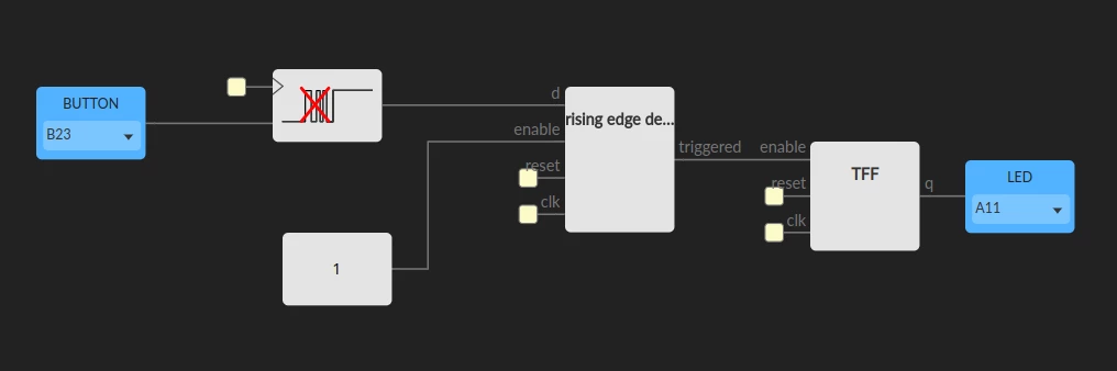
1. Button and LED are still on B23 and A11.
2. The Button is connected to a strange block with a picture. It is a debouncer. Yes, we did not cover it (…Yet) but don’t panic, it is available in the default block on the left. Just click on the blue lego block on the left->default collection->Logic->Sequential->Debouncer. For the “1” block default collection-> bit->1.
3. verify, build, load. You did it.
Conclusion
I did not put a Verilog/VHDL code of the finished project on purpose. Because learning with blocks is the best way to learn FPGA design, in my opinion. By directly placing DFF and gates on a canvas, you really see what you are putting in your FPGA. VHDL and Verilog are Event Description Language not Hardware Description Language : “if enable is asserted assign d to q” is not a hardware part of your FPGA, it is the description of an event. This event will be translated by the synthesizer to a DFF later. If you learn to design only with VHDL or Verilog without knowing what happens under the hood, I bet your future designs will be at best sub-optimized or it won’t work at all. And it is also a good way to initiate software developers to FPGA design, I remember having a hard time understanding the difference between “for loops” in HDL and General Purpose Language when I was a student with only software background. With blocks, there is no ambiguity.