Hello FPGAmigos ! As a student, my final FPGA project was “Space Invader”. We only tackled a small portion of the entire project because our instructor felt certain aspects were too complex for us, and the VGA interface was one such area (which seems utterly absurd in hindsight). My inexperienced self, freshly introduced to the mysteries of VHDL, took his word for it after merely glimpsing the daunting module filled with boilerplate code. From that moment, the VGA interface remained shrouded in an unwarranted aura of complexity in my mind. That was until I faced my GoBoard from Nandland, equipped with a VGA interface, compelling me to confront this “veteran wolf” that once intimidated my level 1 wizard self.
I decided to deviate from the standard VGA tutorial on Nandland. Instead of following it, I only referred to the VGA overview and constants. The tutorial on Nandland is presented in VHDL and Verilog, and since I’m not a fan of either, I chose to approach it with Chisel! Even if you don’t have an FPGA with a VGA interface or a VGA monitor, you can still follow. I have included a cocotb simulation at the end of this article to visualize the outcomes.
In this session, I’m experimenting with a new method: I’ll be using Python pseudo-code for explanations, catering to those more comfortable with software than hardware. Let me know how you find this approach.
If you’re new to Chisel and eager to try it out, feel free to explore my other blog posts:
- Chisel types and operators
- Chisel Multiplexers Tutorial
- Chisel Registers Tutorial
- A little project LEDs garland with ShiftRegister
What is VGA ?
VGA, an acronym for Video Graphics Array, is a video interface standard originally launched by IBM. It quickly rose to popularity and served as the precursor to modern interfaces like DVI, HDMI, and DisplayPort. If you have an older or budget-friendly display monitor, take a look at its back. You’ll likely find a blue, trapezoid-shaped connector—that’s the VGA port.

How to design a VGA module ?
As always the code is available on my Github.
Nested for loops to traverse the image
The underlying principle of VGA is straightforward. An image is essentially a two-dimensional array of pixels, each defined by RGB (Red, Green, Blue) values. The VGA protocol displays these images by printing each frame pixel by pixel, following a left-to-right and top-to-bottom order. For this example, we’ll set the resolution to the standard 640×480.In Python, this can be effectively represented using two nested for loops:
# pseudo code
total_column  = 640 #image width
tolal_row     = 480 #image height
for column in range(total_column):
	for row in range(tolal_row):
		send_monitor(pixel, column, row)
In Chisel, the concept of two nested for loops can be translated into two counters. Below is an implementation of a counter that increments when the ‘enable’ signal is asserted. Additionally, this counter emits a “trig” signal upon reaching the ‘max_count’ value:
class Counter(max_count: Int) extends Module{
val io = IO(new Bundle{
	val enable = Input(Bool())
	val count = Output(UInt(log2Ceil(max_count).W))
	val trig = Output(Bool())
})

val reg_count = RegInit(0.U(log2Ceil(max_count).W))
when(io.enable){
	reg_count := Mux(reg_count===max_count.U, 0.U, reg_count+1.U)
}
io.count := reg_count
io.trig  := reg_count===max_count.U
}
To emulate the effect of a nested loop, we require two counters, similar to the one described earlier. In this setup, the ‘trig’ signal from the first counter is connected to the ‘enable’ input of the second counter. The ‘col_counter’ operates as a free counter (continuously counting without stopping, hence ‘enable := true.B’), while the ‘row_counter’ increments only when the ‘col_counter’ reaches its ‘max_count’.
case class VgaConfig(
//instantiated at the end of the post ;)
TOTAL_COL : Int,
TOTAL_ROW : Int,
}
// Pseudo code for nested for loop in chisel
class NestedForLoop(config: VgaConfig) extends Module{
	// ios ...

	val col_counter   = Module(new Counter(config.TOTAL_COL))
	val row_counter   = Module(new Counter(max_count=TOTAL_ROW))
	// col_counter is a free counter
	col_counter.io.enable := true.B
	// row_counter increment only when col_counter reach the line end
	row_counter.io.enable := col_counter.io.trig
}
Now that we have established the structure to traverse the frame, the next question arises: How do we synchronize our FPGA source with our VGA monitor? If a continuous stream of pixels is sent, how will the VGA monitor distinguish when a new line or a new frame begins? This is where the necessity of adding synchronization signals comes into play.
Introducing Hsync and Vsync
In VGA technology, there are two critical synchronization signals: hsync (Horizontal sync) and vsync (Vertical sync). When hsync is set to 1, it signals to the monitor that the current column is valid for pixel display. Similarly, when vsync is 1, it indicates that the current row is valid. The monitor will display a given pixel only if it falls within this valid zone, meaning both hsync and vsync need to be 1. Additionally, hsync and vsync also have intervals where they must be set to 0. This requirement leads to the concept of what I call a “virtual frame,” which is larger than the actual image we want to display. For instance, we might use a virtual frame size of 800×525.
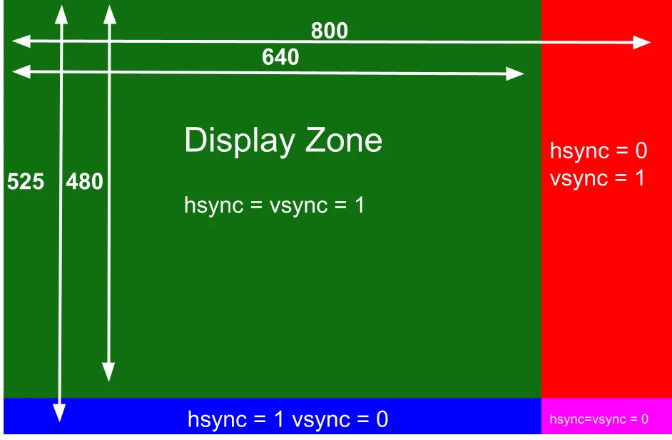
This concept can be translated into the following pseudo-code:
active_column  = 640
active_row     = 480
total_col      = 800
tolal_row      = 525

for column in range(total_column):
	for row in range(total_row):
		hsync = 1 if column<active_column else 0
		vsync = 1 if row<active_row else 0

		active_zone = hsync & vsync
		if active_zone:
			send_monitor(pixel, hsync, vsync)
		else:
			# when inactive, the rgb signals should be driven low.
			send_monitor(0 , hsync, vsync)
In Chisel, the implementation of this concept would be structured as follows:
case class VgaConfig(
	TOTAL_COL : Int,
	TOTAL_ROW : Int,
	ACTIVE_COL : Int,
	ACTIVE_ROW : Int,
}
// Pseudo code
class SyncPulse(config: VgaConfig) extends Module{
	val io = IO(new Bundle{
		val hsync = Output(Bool())
		val vsync = Output(Bool())
		val active_zone = Output(Bool())
	})

	// NESTED FOR LOOP HERE
	// ...

	// HSYNC & VSYNC
	val hsync = Wire(Bool())
	val vsync = Wire(Bool())
	// Just add two comparator
	hsync := col_counter.io.count <= config.ACTIVE_COL.U
	vsync := row_counter.io.count <= config.ACTIVE_ROW.U
	// Driving output
	io.hsync       := hsync
	io.vsync       := vsync
	io.active_zone := hsync & vsync
}
Indeed, the process essentially involves adding two comparators to generate the hsync and vsync signals. Hsync is set to 1 when the column counter is less than 640, applying the same logic for vsync and ACTIVE_ROW.
Now, you might think our VGA monitor is synchronized, but unfortunately, it’s not that simple. Working with hardware often involves additional complexities. While I’m not fully versed in the specifics (I believe it relates to allowing the electron beam in cathode ray tube monitors to return to the start of the screen), our monitors require a buffer period after the end of each column and row, during which hsync and vsync remain active. Additionally, the monitor needs hsync and vsync to be asserted briefly before the start of a new line or column. These periods are known as the front porch and back porch, and they differ for hsync and vsync.

Green represents the active zone, and each different color indicates a specific type of porch: pink for the front porch horizontal, orange for the back porch horizontal, light blue for the front porch vertical, and yellow for the back porch vertical. Black areas indicate times when one or both sync signals are actually set to 0.
In pseudo-code, this concept translates to adding four comparators. These comparators check whether the column and row counters are outside the ranges specified for these porches.
active_column  = 640
active_row     = 480
total_col      = 800
tolal_row      = 525
FPH = 16 # Front Porch Hsync
FPV = 10 # Front Porch Vsync
BPH = 48 # Back Porch Hsync
BPV = 33 # Bach Porch Vsync

for column in range(total_column):
	for row in range(total_row):
		hsync = 1 if column<active_column else 0
		vsync = 1 if row<active_row else 0
		hsync_porch = 0 if active_column+FPH<=column<=total_column-BPH else 1
		vsync_porch = 0 if active_row+FPV<=row<=total_column-BPV else 1

		active_zone = hsync & vsync
		if active_zone:
			send_monitor(pixel, hsync_porch, vsync_porch)
		else
			send_monitor(0    , hsync_porch, vsync_porch)
In Chisel, the implementation of this concept would be structured as follows:
case class VgaConfig(
TOTAL_COL : Int,
TOTAL_ROW : Int,
ACTIVE_COL : Int,
ACTIVE_ROW : Int,
FPH : Int,
FPV : Int,
BPH : Int,
BPV : Int
)
//the counter here ...
class SyncPulse(config: VgaConfig) extends Module{
// ios and add hsync and vsync porch
val io = IO(new Bundle{
// ... same as before
val vsync_porch = Output(Bool())
val active_zone = Output(Bool())
})
// NESTED FOR LOOP...
// HSYNC and VSYNC...
// HSYNC_PORCH and VSYNC_PORCHES
val hsync_porch = Wire(Bool())
val vsync_porch = Wire(Bool())
// hsync with porch
hsync_porch := col_counter.io.count <= config.ACTIVE_COL.U + config.FPH.U ||
col_counter.io.count >= config.TOTAL_COL.U - config.BPH.U
// vsync with porch
vsync_porch := row_counter.io.count <= config.ACTIVE_ROW.U + config.FPV.U ||
row_counter.io.count >= config.TOTAL_ROW - config.BPV.U
// Drive outputs
// ... other outputs +
io.hsync_porch := hsync_porch
io.vsync_porch := vsync_porch
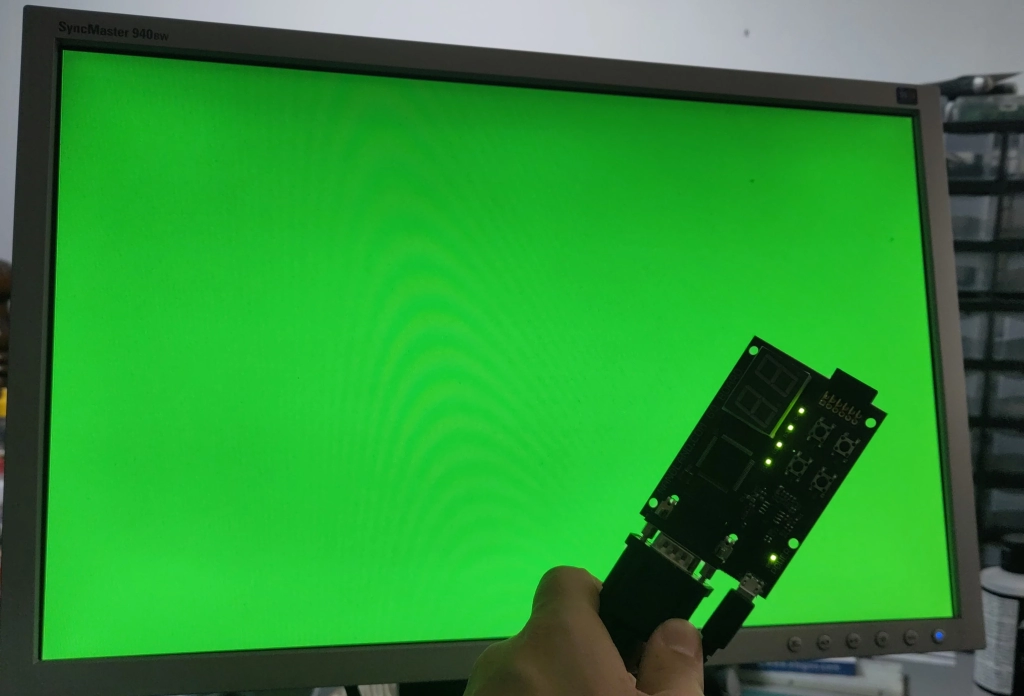
}And now it should work! That’s really all it takes: two counters and six comparators, and you have a functional VGA setup. The next step is to encapsulate this configuration in a module and use it to display an image—in our example, a simple green screen.
class VGABundle extends Bundle{
val red   = Output(UInt(3.W))
val green = Output(UInt(3.W))
val blue  = Output(UInt(3.W))
val hsync = Output(Bool())
val vsync = Output(Bool())
}

class VGA(config: VgaConfig) extends Module{
	val io = IO(new VGABundle)
	val sync_pulse = Module(new SyncPulse(config))
	// rgb signals should be driven low outside the active_zone hence the mux
	io.red   := Mux(sync_pulse.io.active_zone, 1.U, 0.U)
	io.green := Mux(sync_pulse.io.active_zone, 7.U, 0.U)
	io.blue  := Mux(sync_pulse.io.active_zone, 1.U, 0.U)
	io.hsync := sync_pulse.io.hsync_porch
	io.vsync := sync_pulse.io.vsync_porch
}

// The Top only to set the clock domain
class Top(config: VgaConfig) extends RawModule {
	val clock  = IO(Input(Clock()))
	val vga_io = IO(new VGABundle)
    // no reset on GoBoard
	withClockAndReset(clock, false.B){
		val vga = Module(new VGA(config))
		vga_io  <> vga.io
		}
}

// The main that generate the verilog
object Main extends App{
	val vga_config = VgaConfig(
		TOTAL_COL  = 800,
		TOTAL_ROW  = 525,
		ACTIVE_COL = 640,
		ACTIVE_ROW = 480,
		FPH        = 16,
		FPV        = 10,
		BPH        = 48,
		BPV        = 33
	)
	(new chisel3.stage.ChiselStage).emitVerilog(new Top(vga_config), Array("--target-dir", "build/artifacts/netlist/"))
}
Generate a frame with Cocotb
If you don’t have a GoBoard or any VGA connector, cable, or similar equipment, and yet you’re still eager to witness the marvel of a green screen, don’t worry! Cocotb and Verilator are here to help. If you are unfamiliar with cocotb, go check my blog post “How to write your first Cocotb Testbench“.
Originally, I planned to write a testbench in case of any bugs in my design. However, as I vanquished the “veteran wolf” of VGA complexity now that I am a wizard level ?? (you tell me haha), I didn’t encounter any issues to troubleshoot… . Nonetheless, this experience serves as a foundation for my next tutorial (perhaps a Conway’s Game of Life) and as a tool for you to verify if your design works as intended.
# Cocotb import
import cocotb
from cocotb.triggers import RisingEdge
from cocotb.clock import Clock
# Import to create image
from PIL import Image
import numpy as np

@cocotb.test()
async def dump_frame(dut):
	# Declare and start the simulation Clock
	clock = Clock(dut.clock, 40, units="ns")
	cocotb.start_soon(clock.start())

	# Variable declaration
	num_cycles = 800*525 # one frame
	rgb_frame  = []
	pixel_line = []
	col        = 0
	row        = 0

	# For loop : every pixel of a frame
	for cycle in range(num_cycles):
		await RisingEdge(dut.clock)
		# Get value from dut
		hsync = int(dut.vga_io_hsync)
		vsync = int(dut.vga_io_vsync)
		red   = int(dut.vga_io_red)
		green = int(dut.vga_io_green)
		blue  = int(dut.vga_io_blue)

		# Pixel in pillow a Uint8 whereas they are 3 bits in my design.
		# We need a shift to see something
		pixel = [red<<4,green<<4,blue<<4]

		col+=1
		pixel_line.append(pixel)
		if col==801:
			rgb_frame.append(pixel_line)
			pixel_line = []
			col=0
			row+=1

	# Creating the frame with pillow and numpy
	frame     = np.array(rgb_frame, dtype=np.uint8)
	new_image = Image.fromarray(rgb_frame)
	new_image.save("vga_frame.png")
Conclusion
And there you have it, fellow FPGAmigos ! We’ve journeyed through the realm of VGA, transforming a seemingly complex topic into an understandable and approachable project. From counters to comparators, and finally to the grand unveiling of a green screen, our expedition into the world of Chisel and VGA has been both enlightening and rewarding.
Remember, the world of FPGA isn’t just about conquering technical mountains—it’s also about the thrill of discovery and the satisfaction of solving puzzles that once seemed daunting. As we wrap up this tutorial, I hope you feel empowered to tackle your own FPGA projects, no matter how challenging they may seem at first glance.
Stay curious, keep experimenting, and don’t forget to share your FPGA conquests with the community. Whether you’re a novice wizard or a seasoned sorcerer in the FPGA realm, there’s always a new adventure waiting around the corner. Until next time, keep exploring and happy coding!