Hello FPGAmigos! In our last session, we explored SBY and formal verification. I planned to show you the bug that SBY detected, but the post became too lengthy with numerous topics. Today, we’ll have a “leftover” blog post, focusing on the material I didn’t cover previously.
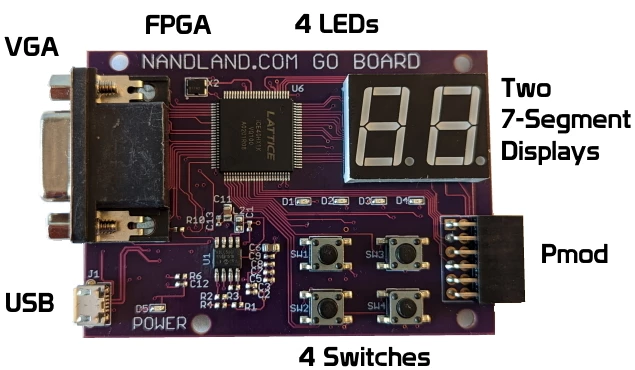
Firstly, we’ll dive into how to use the GoBoard, developed by Russel Merrick of Nandland. There’s a comprehensive tutorial available for the GoBoard on Nandland, though it’s designed for Windows users. I’ll adapt it for Linux and open-source tools to make it accessible to everyone.
Secondly, we’re going to intentionally provoke the bug in our design to provide a visual understanding of its effects. Generally, bugs in FPGAs are hidden, observable only through waveforms and logs. However, it’s quite rewarding to create a scenario where the bug’s impact is visible to the naked eye.
The Design
As always you can find the source code on my github page.
Let’s begin with the design. We’re working with a straightforward setup consisting of two counters: the first generates a pulse every second, and the second, activated by the first, counts from 0 to 15. The value of the second counter is then displayed on a 7-segment display.
Below is the buggy counter we discussed last time:
class Counter(max_count: Int) extends Module{
val io = IO(new Bundle{
	val enable = Input(Bool())
	val count = Output(UInt(log2Ceil(max_count).W))
	val pulse = Output(Bool())
})
val reg_count = RegInit(0.U(log2Ceil(max_count).W)
when(io.enable){
	reg_count := Mux(reg_count===max_count.U, 0.U, reg_count+1.U)
	// fixed version
	// io.pulse := reg_count === max_count.U
}
io.count := reg_count
io.pulse := reg_count === max_count.U
// fixed version
// io.pulse := 0.U
}
The module responsible for the seven segment display:
class SevenSegment extends Module{
val io = IO(new Bundle{
	val digit = Input(UInt(4.W))
	val segment = Output(UInt(7.W))
})
/* Seven segment names
 *    --a--
 *   |     |
 *   f     b
 *   |     |
 *    --g--
 *   |     |
 *   e     c
 *   |     |
 *    --d--
 */
val reg_segment = RegInit(0.U(7.W))
switch(io.digit){
	//                         abcdefg
	is(0.U)  {reg_segment := "b1111110".U} // 0
	is(1.U)  {reg_segment := "b0110000".U} // 1
	is(2.U)  {reg_segment := "b1101101".U} // 2
	is(3.U)  {reg_segment := "b1111001".U} // 3
	is(4.U)  {reg_segment := "b0110011".U} // 4
	is(5.U)  {reg_segment := "b1011011".U} // 5
	is(6.U)  {reg_segment := "b1011111".U} // 6
	is(7.U)  {reg_segment := "b1110000".U} // 7
	is(8.U)  {reg_segment := "b1111111".U} // 8
	is(9.U)  {reg_segment := "b1111011".U} // 9
	is(10.U) {reg_segment := "b1110111".U} // A
	is(11.U) {reg_segment := "b0011111".U} // b
	is(12.U) {reg_segment := "b1001110".U} // C
	is(13.U) {reg_segment := "b0111101".U} // d
	is(14.U) {reg_segment := "b1001111".U} // E
	is(15.U) {reg_segment := "b1000111".U} // F
}
// i released afterward they were active-low ^^'
io.segment := ~reg_segment
}
The Top with which trigger the bug:
class Top extends Module {
	val io = IO(new Bundle{
		val segment = Output(UInt(7.W))
	})
val tick_counter  = Module(new Counter(25000000))
val digit_counter = Module(new Counter(15))
val seven_segment = Module(new SevenSegment)

// implementation without bug
// tick_counter.io.enable := true.B

// implementation that trigger bug
tick_counter.io.enable := ~tick_counter.io.pulse

// stay the same
digit_counter.io.enable := tick_counter.io.pulse
seven_segment.io.digit := digit_counter.io.count
io.segment := seven_segment.io.segment
}
How to remove reset in chisel ?
Let’s now focus on the top module for the GoBoard that highlights a particular feature of Chisel. Interestingly, the GoBoard doesn’t have a reset button (or at least none that I’m aware of). This presents a perfect opportunity to explore how to manage a module without an implicit reset in Chisel:
class GoBoardTop extends RawModule {
	val io = IO(new Bundle{
		val clock = Input(Clock())
		val segment = Output(UInt(7.W))
})
// the GoBoard has no reset
withClockAndReset(io.clock, false.B){
	val top = Module(new Top)
	io.segment := top.io.segment
}
}
Firstly, it’s important to note that the GoBoardTop class inherits from RawModule instead of the more conventional Module. The reason for this is that Module automatically assumes you’re using the system’s default clock and reset signals. However, RawModule requires you to explicitly define them.
Moving to the I/O section, you’ll need to declare an input for the clock. You can name it clock or choose another name, but what’s crucial is the type of this input—it should be Clock(), not Bool or UInt.
After defining your clock input, we use the withClockAndReset function to create a scope where we can specify our chosen clock and the deliberate omission of a reset signal. You simply pass our io.Clock as the first argument and false.B to signify that there is no reset. Every module defined within this scope will then use the clock and the “no reset” condition we’ve set.
GoBoard workflow
We’ll be following the same workflow from From HDL to bitstream and simply adapt it for the GoBoard.
For synthesis, all you need to do is update the source file and the name of the Top module.
read -sv build/artifacts/netlist/GoBoardTop.v
hierarchy -top GoBoardTop
proc; opt; techmap; opt
synth_ice40 -top GoBoardTop -json build/artifacts/syn/synth.json
The main change in the process occurs during the place and route step, where you’ll need to specify the device family and package for the GoBoard. Russell has conveniently provided this information in the header of the GoBoard.pcf file. If you’re ever unsure, or if you’re working with a different FPGA, this information is typically printed on the FPGA itself—although you might need a magnifying glass to read it.
nextpnr-ice40 --hx1k --package vq100 --json ./build/artifacts/syn/synth.json --pcf ./src/constraints/GoBoard.pcf --asc ./build/artifacts/pnr/top.asc --freq 25Remember to adjust the clock frequency; otherwise, your seconds may not measure as expected—they could end up being quite brief!
Also, be sure to update the signal names in the .pcf file to match your design.
### Main FPGA Clock
set_io io_clock 15

# Left seven segment
set_io io_segment[0] 2
set_io io_segment[1] 1
set_io io_segment[2] 90
set_io io_segment[3] 91
set_io io_segment[4] 93
set_io io_segment[5] 4
set_io io_segment[6] 3
Bitstream generation and loading the bitstream stay the same:
# bistream generation
icepack ./build/artifacts/pnr/top.asc ./build/artifacts/bitstream/bitstream.bin
And the load command:
iceprog ./build/artifacts/bitstream/bitstream.binTriggering the bug
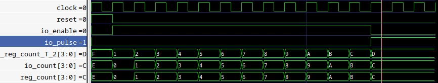
The bug that formal verification uncovered (in the last blog post ) occurs when the enable signal is turned off at the exact moment the pulse signal turns on. If this happens, the counter stops at “count == max_count” along with the pulse signal.
Under this condition, to trigger the bug, we simply need to connect the inverse of tick_counter.io.pulse to tick_counter.io.enable.
// implementation that trigger bug
tick_counter.io.enable := ~tick_counter.io.pulse
So, what will happen now?
The first counter is supposed to generate a pulse every second. However, after the first pulse, the enable signal is deactivated, making the pulse stay high. The second counter is designed to increment with each pulse, but now, since the pulse signal stays high, the second counter increases with every clock cycle instead of once every 25 million clock cycles.
And the result? The seven-segment display appears to be stuck on the number 8, but it is not the case, it counts so rapidly that it looks like the segments never turn off to the human eye.
The bug:
The expected behavior :
You can clearly observe that the counter begins at 0 as intended, but after one second, the bug is triggered and the seven-segment display shows an 8.
Conclusion
As we come to the end of this post, we’ve taken a deeper dive into the intricacies of FPGA design with the GoBoard, challenged ourselves with clock management in Chisel, and illuminated a sneaky bug that taught us a valuable lesson about signal synchronization.
For those who missed the earlier discussion that led to this point, I invite you to read the previous blog post here. It sets the stage for why we dove deeper into this particular bug and provides context that enriches today’s findings.
Remember, every mistake is a learning opportunity, and every ‘leftover’ piece of knowledge is a building block towards mastery. Until our next post, keep experimenting and learning!